Three.js: GLTFLoader: Normal-Tangent Test model result is incorrect
Description of the problem
I tried to display the Normal-Tangent Test model.
However, the displayed result seems to be different from Khronos' sample.
Three.js + Normal-Tangent Test model result:

Khronos sample loader + Normal-Tangent Test model result:

I think that this sample model should have the same left and right results.
Related : https://emackey.github.io/testing-pbr/normal-tangent-readme.html
/cc @emackey
Three.js version
- [x] Dev
- [ ] r85
- [ ] ...
Browser
- [x] All of them
- [ ] Chrome
- [ ] Firefox
- [ ] Internet Explorer
OS
- [x] All of them
- [ ] Windows
- [ ] macOS
- [ ] Linux
- [ ] Android
- [ ] iOS
Hardware Requirements (graphics card, VR Device, ...)
ThinkPad X260 + Windows 10 + Intel HD Graphics 520
 cx20
cx20
All 30 comments
Thanks for writing this up @cx20.
Just for more context, here are some related info & issues:
I reported a similar issue on @donmccurdy's ThreeJS glTF viewer, donmccurdy/three-gltf-viewer#10. But I now think this is a bug in ThreeJS's glTF loader, not in the viewer. So, this new issue is better placed than my old issue.
In the above older issue, the model used to face the sky, but later I rotated it to face the horizon. This makes it easier to see when the reflections aren't right, because the horizon rotates around crazily, as shown above.
The model's own use of a normal map was confirmed correct by discussion in KhronosGroup/glTF#952.
ThreeJS's handling of normal maps was questioned in #11315.
BabylonJS recently had a similar problem, reported here, and fixed here. Here's a live demo of BabylonJS's glTF 2.0 loader with the fix applied.
 emackey
on 3 Jun 2017
emackey
on 3 Jun 2017
Good writeup, thanks!
The model appears to render correctly with the addition of this line:
materialParams.normalScale = new THREE.Vector2(-1, 1);
But I'm not sure I understand the issue well. Understanding #11315 might help here.
 donmccurdy
on 3 Jun 2017
donmccurdy
on 3 Jun 2017
@donmccurdy Thanks for your advice.
I understood that improving by adjusting normalScale.
However, if glTF model is correct, I think that it is better for glTF Loader to handle it.
cx20
on 22 Jul 2017
@cx20 agreed, this fix is now merged into THREE.GLTF2Loader.
donmccurdy
on 23 Jul 2017
I have confirmed that it is being fixed.
 cx20
on 23 Jul 2017
cx20
on 23 Jul 2017
This has regressed, sometime between r101 and r104:

 elalish
on 12 Jun 2019
elalish
on 12 Jun 2019
See https://github.com/mrdoob/three.js/pull/15749 — the regression is intentional, and can be avoided by including tangents in the model.
Ideally we would have a JS implementation for generating mikktspace tangents, to fully solve this, but that is fairly complex.
donmccurdy
on 13 Jun 2019
I wasn't aware of #15749 until now. I'm caught off guard by this, I had thought we did a good enough job defining the tangents in glTF that they could be at least approximated at runtime.
Note that the Blender exporter won't export any glTF tangents by default, as it helps keep the file size down, and the major implementations of glTF were all passing this test without tangents. I suspect this change may have broken normal mapping for a majority of glTF models in ThreeJS.
I'll need some time to read through all the linked issues to get a deeper understanding of what's happened and why. But I think the glTF community should consider this high priority to get models without tangents rendering correctly again, as I believe most models are in that category by default.
emackey
on 13 Jun 2019
Reopening 😅
 mrdoob
on 13 Jun 2019
mrdoob
on 13 Jun 2019
I suspect this change may have broken normal mapping for a majority of glTF models in ThreeJS.
I don't believe it's anything that severe – we've always generated tangents realtime in the shader with derivatives, and we still do. We previously included a hack (normalScale.y *= -1) that happened to fix this specific test model, but also happened to break some other examples. I have no explanation for when that helped, or didn't, so we removed the hack once we supported stored tangents – in which case it would certainly have been wrong. Now the models that relied on the hack (and don't include tangents) are broken, and models that were broken by the hack (and don't include tangents) are fixed.
But I think the glTF community should consider this high priority to get models without tangents rendering correctly again, as I believe most models are in that category by default.
See above. In general, I believe we do render models without tangents adequately. We do not, however, generate mikktspace tangents as required by the glTF spec. To my knowledge, no JS implementation of that exists, and our derivatives-based shader implementation is simply a "mostly good enough" approximation. This sample model is an intentionally extreme case that demonstrates the limits of that approximation.
We'd be glad to have a JS mikktspace tangent generation implementation; that would be good addition to THREE.BufferGeometryUtils. But the official (native) mikktspace code is fairly long, and I haven't dug in enough yet to see how much of that is required for generating tangents.
donmccurdy
on 14 Jun 2019
We previously included a hack (
normalScale.y *= -1) that happened to fix this specific test model, but also happened to break some other examples
Did it break other glTF models specifically, or just examples in general?
There are two different types of tangent-space normal maps out in the wild. Substance Painter calls these "DirectX Normals" and "OpenGL Normals", which is not the greatest name for it. The difference is specifically the y channel is inverted, meaning all of the green channel values in the texture are inverted. Multiplying y *= -1 is the correct way to convert one to the other. The so-called "DirectX Normals" use a left-handed coordinate system, and glTF defines a right-handed coordinate system for normal/tangent/bitangent.
What I suspect is happening is that when ThreeJS auto-calculates tangents, it expects the normal map to have been authored with the flipped Y (DirectX) style, and gets that channel backwards for glTF, so the flip is needed. However, when the tangents are supplied, no such flip is needed.
The question of mikktspace I think is separate from this. It's unfortunate that the spec calls for mikktspace and most implementations approximate that with screen-space derivatives. I don't know how similar the two are, but, normal maps generated in mikktspace appear to work reasonably well when shown with the approximation, so long as the left/right-handedness of the map is done correctly.
(There's also some discussion of this from last year in KhronosGroup/glTF-Sample-Models#174)
emackey
on 14 Jun 2019
I'd like to call out one sentence from the glTF spec on normal maps in particular:
The normal vectors use OpenGL conventions where +X is right and +Y is up. +Z points toward the viewer.
This sentence is what allows models to be shipped without tangent vectors, saving space.
Let's test it. Here I've made a lousy height map (bump map) out of a splotch in a paint program:

Let's define this height field as an outward bump, where white pixels are closer to the viewer, and black pixels are further away.
Using an online converter (of questionable quality, but we'll examine the result in a moment), I've converted this from a height map to a normal map. Keep in mind there's no 3D model here, no UV coordinates or mikktspace calculations or any geometry. Just a height map converted to a normal map. I had to manually configure the online converter per glTF's instructions, such that X is right, Y is up, and Z faces the viewer. This is the result:

Let's bring that back into a paint program and bust out the color channels to see where these vectors point. Below, each color channel has been separated into a grayscale image of its own. Remember that these will be interpreted such that black means -1.0, middle gray means 0.0, and white means +1.0.
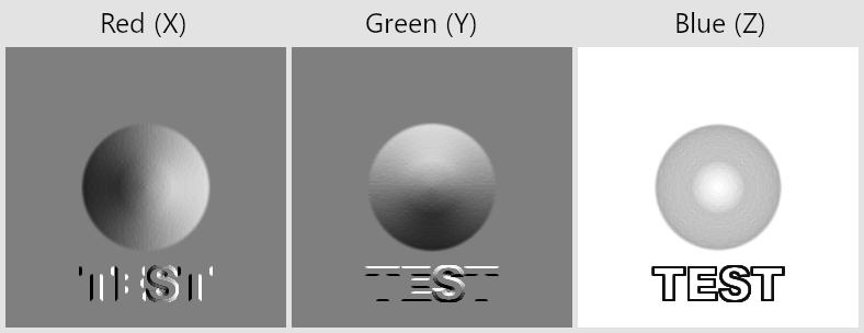
So I think the online converter did what glTF asked, at least after configuring it correctly. In the Red (X) image, we can see the slope on the right has white pixels (+1.0), pointing the X vector at the right edge of the image. On the left side of the Red image, black pixels (-1.0) point the X vector at the left side of the image. In the Green (Y) image, white pixels along the top slope of the bump point the Y vector at the top of the image. The Z values are the least intuitive, but remember that the tip of the bump and the back plate itself both point at the viewer, and the slopes on all sides point away, so are all evenly darker.
What if we load this into Blender Eevee, which (just like glTF) accepts OpenGL-style normal maps? What happens if the UV map is rotated, or even scaled to be inverted?
Turns out, this works just fine. Indeed, the whole point of defining the tangent space this way is not to enable software to go crazy with the vectors, it's to allow texture artists some sanity by ensuring that their normal maps will be right-side up regardless of the geometry.
But, not all software uses the OpenGL convention. Some uses a different convention (sometimes called the DirectX convention), where the Y vectors point at the bottom of the image instead of the top. Here's the decomposed Y channel of my image in this form. The lighter pixels are the ones facing the bottom of the image.

If I load one of these DirectX-style normal maps into Blender Eevee, can I still expect it to work?
No. Blender was expecting +Y up. The math is wrong, and the reflected horizon line spins all around.
The same thing happens if you load an OpenGL-style normal map into an engine that was expecting +Y down.
This is what the NormalTangentTest model is attempting to test. Each row spins the UV coordinates into a different orientation, trying to make sure that the reflections remain right-side up in these different orientations.
emackey
on 14 Jun 2019
There still needs to be a concrete formula in the specification for how to compute a tangent for a lone primitive, given a primitive and its UV coordinates, and which W sign to use for bitangent. "OpenGL normals" and "DX normals" is not precise enough to derive the formula. They might refer to conventions, but I have no idea as an implementer what to do with that.
What I currently do is emit flipped TangentW from MikkTSpace to match up with this particular sample, but that was just what happened to work.
 Themaister
on 18 Jun 2019
Themaister
on 18 Jun 2019
Did it break other glTF models specifically, or just examples in general?
Reported bugs were related to glTF models, specifically. That said, I doubt there's enough confidence in material export via FBX or COLLADA to say those normal map conventions were ever thoroughly understood and tested either.
The difference is specifically the y channel is inverted, meaning all of the green channel values in the texture are inverted. Multiplying y *= -1 is the correct way to convert one to the other.
Thanks, this is a much better justification of our "hack" than we had when we implemented it. 😇
It's unfortunate that the spec calls for mikktspace and most implementations approximate that with screen-space derivatives.
The spec is right that MikkTSpace is the most robust way to generate tangents, I think, it's just not universally the right choice to do this automatically at runtime. If cheaper alternatives look correct for a particular model, there's no reason to do something more expensive that doesn't look any better. The spec language could be loosened to allow for approximations but I don't feel strongly about this.
There still needs to be a concrete formula in the specification for how to compute a tangent for a lone primitive, given a primitive and its UV coordinates, and which W sign to use for bitangent.
I'm not sure the MikkTSpace algorithm is so easy to represent as a discrete formula... are you asking for an alternative to the canonical MikkTSpace code? Or some additional information beyond the instruction to use MikkTSpace? @Themaister
For the original issue, it sounds like we ought to restore the normal.y *= -1 multiplier somewhere. There are three possible places to do this:
- (a) in GLTFLoader, for meshes that do not have tangents
- (b) in GLTFLoader, for all meshes
- (c) in WebGLRenderer, for all meshes
If threejs is really using the DirectX convention and e.g. Blender is not, I could see a case for (c). In the interest of a quick and safe solution, though, I am inclined to go with (a).
donmccurdy
on 27 Jun 2019
What I suspect is happening is that when ThreeJS auto-calculates tangents, it expects the normal map to have been authored with the flipped Y (DirectX) style.
No, three.js does not assume that...
three.js assumes +Y is "up" for tangent space, and increasing-V is "up" for uv space.
That is, three.js assumes uv ( 0, 0 ) is in the lower-left corner of the texture, while the glTF spec assumes the upper-left. This is why GLTFLoader sets texture.flipY to false. (three.js sets texture.flipY to true by default.)
When tangents are not present, three.js uses screen-space derivatives to estimate tangents. It does so using the chain rule. An assumption in that calculation is that tangent space and uv space have the same orientation.
For properly-authored glTF models, that assumption is not correct. However, you should be able to compensate by setting normalScale.y = - 1 for any model that _properly adheres to the glTF spec_.
It would also seem to me we could fix this automatically by honoring the flipY flag in the shader.
If setting normalScale.y is not working, then something else is going on.
 WestLangley
on 30 Jun 2019
WestLangley
on 30 Jun 2019
Thanks for this clarification. I think we have a path forward here.
It would also seem to me we could fix this automatically by honoring the
flipYflag in the shader.
Yes, with the exception of cases where the glTF supplies its own tangent vectors, right? I would expect only the auto-computed tangents to need the flipY test and corresponding negation of y.
If that's not the case... that would mean that my NormalTangentMirrorTest model has incorrect tangents encoded into it, meaning the Blender glTF exporter itself is putting the wrong tangents into glTF models. Blender is using a lower-left origin, and off the top of my head I don't know if that means the tangent vectors themselves must be edited or not before copying into the model (and whether the exporter performs such edits).
Edit: I believe I've confirmed the correctness of the exported tangent vectors, and they do not need any Y flipping. I can post more detail on that if needed.
But it seems like the correct action is to flip normalScale.y only when auto-generated tangents (not supplied tangents) are being used with the flipY flag. Thoughts?
emackey
on 30 Jun 2019
In my previous post, I explained how to manually compensate for inverted normals when attribute tangents are not present. There should be nothing to compensate for when tangents are present because screen-space derivatives are not being used.
I also suggested we may be able to fix this automatically by honoring the flipY flag in the shader. I did not say we would fix this automatically be flipping normalScale.y, however. I do not think we should alter the user's settings.
In any event, before we go down that path, I think it is imperative that we verify this hypothesis:
[Y]ou should be able to compensate by setting normalScale.y = - 1 for any model that properly adheres to the glTF spec.
We must have an explanation for every model that is not being rendered correctly.
WestLangley
on 30 Jun 2019
I do not think we should alter the user's settings.
Yes, apologies, I did not intend to be dictating that sort of implementation detail. I'm just trying to make sure there's not a misunderstanding of what _honoring the flipY flag_ means mathematically, for the purpose of screen-space tangent generation.
We must have an explanation for every model that is not being rendered correctly.
That sounds like that could potentially be a large set. If there are indeed models out there that are doing something radically different than the official test models, and yet could still be considered valid uses of normal maps in glTF, that would be important to discover. The test models are intended to cover valid uses of normal maps on static (non-transformed) geometry. There shouldn't be a way, particularly when relying on viewer-generated tangent vectors, to construct the model in some other coordinate system and yet claim that it's valid glTF.
emackey
on 9 Jul 2019
I assume this is closely related to this issue? https://github.com/KhronosGroup/glTF-Sample-Models/issues/174
elalish
on 10 Jul 2019
@WestLangley Here's what I've found so far. By default, khronos-NormalTangentTest (no tangents included) looks wrong:

If I set normalScale.y = -1, it is still wrong:

If I instead set normalScale.x = -1, it looks correct:

With the possible exception that the rendering looks a bit pixelated, especially on the gold reflector. Is this expected with the screen-space approximation, or an indicator of another bug?
If anyone has any other good test models without tangents, please send them my way. I'd like to make sure I have a representative sample, and determine if there are any that don't fit the glTF spec.
elalish
on 23 Oct 2019
@elalish That testbed does not make sense to me, it has never made sense to me, and it probably never will. So... I will not be of help to you in trying to explain it.
That example is too obfuscated IMHO. We need a coherent test case that provides sufficient visuals to understand what is happening.
BTW, we used to have a VertexTangentHelper (#3511), which could be revived to support buffer geometry.
WestLangley
on 23 Oct 2019
@WestLangley I wish I knew how to make NormalTangentTest more clear. It doesn't do anything outlandish, it simply rotates the orientation (in UV space) of each sample. The three columns are just to test different materials, the gold column could suffice on its own. Other than that I don't think the test model can get much simpler and still test these different UV orientations.
In spite of the UV rotations, the image of the normal map is quite consistent about which way the vectors point, when the normal map as viewed as a 2D image. In a 2D view of the image, the right sides of all the hemispheres have high red-channel values, and the top edges of all hemispheres have high green-channel values, regardless of the UV coordinates. This follows the glTF specification that red (+X) points at the right side of the texture in UV space, and green (+Y) points at the top edge of the texture in UV space. One does not need supplied tangent vectors to make this work: a simple screen-space estimation of generally which direction the +U axis is for a given triangle is sufficient to work out the tangent and bi-tangent vectors, as BabylonJS and CesiumJS do, and of course ThreeJS does as well but with some as yet unexplained normalScale axis flip.
There is a known point of confusion with glTF's use of the flipY flag, inverting V coordinates in UV space, which I believe you're already well aware. I've long suspected this plays a role in the unexplained normalScale flip.
There is also a small baking error in the image (my fault, I was a new user of Substance Painter at the time, years ago). A slight diagonal seam is visible particularly on the flat part of the gold hemispheres. But this shouldn't detract from the overall effect. The main round portion of the bake came out fine, and demonstrates well the effect of "up" and "right" being constant across the entire 2D image of the normal texture, regardless of 3D or UV coordinates being rotated all different directions, and tangents being omitted.
This is an important effect for artists authoring repeating normal map textures prior to 3D geometry being created, as the artist doesn't need access to UV or tangent coordinates in advance of making the texture image.
emackey
on 23 Oct 2019
@WestLangley I like this test only because it's the best I've seen, aka the only. I'll be happy to use any other test model I'm pointed to.
Also, the plot thickens: The original test is a double-sided material. Due to #17804, I decided to try it as single-sided. It's still wrong by default, but now I get the right answer when I set normalScale.y = -1:

At the very least I hope we can agree that changing doubleSided should not affect the front side's render?
elalish
on 23 Oct 2019
@emackey Another test model that could be helpful I think would be a shiny cube with welded normals and a corresponding normal map designed to make it cube-shaped instead of rounded. Probably two versions, one with and one without supplied tangents. Unfortunately I lack the authoring skill to do it myself. All I can offer is many thanks if you make it for us :pray:
elalish
on 23 Oct 2019
@emackey Thank you for all your work on this. I do very much appreciate it. I do understand all the various issues that can arise with artists -- and issues that must be overcome.
Perhaps you would be willing to work with @elalish and provide whatever glb models he requests. I expect that would help us understand.
@elalish We have addressed these issues previously. At one point I was under the impression that everything was working. If there is a simple test case, I can use bisect to identify where things broke.
WestLangley
on 23 Oct 2019
shiny cube with welded normals and a corresponding normal map designed to make it cube-shaped instead of rounded.
Done: normal_map_flat.zip. I took the tangents example, written by the Draco team, and created an extra version without the tangent attribute.
At one point I was under the impression that everything was working.
I think we reached a state where everything works _if_ the model includes tangents. If not, things are usually OK, but there are some edge cases possible especially around UV seams. In that case we would advise users to add tangents. Or, as @emackey mentioned in https://github.com/mrdoob/three.js/issues/11438#issuecomment-507027586, perhaps we should restore the normalScale.y *= -1 flip in GLTFLoader, only in cases where the mesh omits vertex tangents.
donmccurdy
on 23 Oct 2019
@donmccurdy Thanks. I'm out of time for this issue today but I'm still struggling with the flat cube sides. If you edit your model to have a shiny surface (metallicFactor: 1, roughnessFactor: 0.1), you'll see the reflections in the sides of the cube swim around quite a bit.
I'm seeing the same effect in my own test model. Worse, it's a different effect if I do the normal bake in Substance Painter vs. bake it in Blender Cycles. Each program bakes it to be correct for its own viewport, but it's not perfectly flat when loaded into the other program, even without glTF in the mix. It's very close, but on such a flat surface the smallest differences turn it into a funhouse mirror, and not in a good way.
I think I'm seeing a subtle difference in the way normal vectors (or TBN space) is interpolated between vertices across the face of a triangle, in SP vs Blender vs the various WebGL engines. I used Gimp to run a "difference" of an SP bake vs a Blender bake, and it came out black (identical RGB values) at each vertex, but the space in between the vertices shows swirling differences of very faint intensity.
emackey
on 24 Oct 2019
I would expect subtle fun-house effects, but not what I'm getting currently (the no tangents version):

The with tangents version isn't really any better, which leads me to wonder if this is really a valid glTF:

@emackey Do you feel qualified to tell us whether either or both of these models @donmccurdy provided are in fact valid glTF? If they are, I think we have a major problem.
elalish
on 24 Oct 2019
This particular cube is such an extreme example that I don't really know what to say, or whether physically-realistic reflections are a fair expectation. Normal maps are meant for adding details like bumps and dents, not for deforming the entire surface of the mesh. It just happened to be a very effective way to test that tangents get read or generated correctly. I do know that the normalScale.y *= -1 change was never sufficient to fix it; this was one of the examples that prompted us to support stored tangents in the first place.
The reflections look wild in BabylonJS, too:

If the only identified problem is with NormalTangentTest, and no users have come forward with models that render incorrectly in practice, perhaps we should hold off on making a change here?
I'm still OK with restoring the normalScale.y *= -1multiplier, but the lack of examples of the problem seems like an indication that the problem is minor, rather than an indication that we need to create such extreme examples.
donmccurdy
on 24 Oct 2019
If the only identified problem is with NormalTangentTest, and no users have come forward with models that render incorrectly in practice, perhaps we should hold off on making a change here?
Correction: https://github.com/mrdoob/three.js/issues/17804 suggests that something may indeed have regressed with double-sided materials. That seems worth investigating further, although for simplicity and sanity perhaps we should leave the Cursed Cube alone for now. 😇
donmccurdy
on 24 Oct 2019
Related issues
donmccurdy
·
3Comments
 Bandit
·
3Comments
Bandit
·
3Comments
 akshaysrin
·
3Comments
akshaysrin
·
3Comments
 Horray
·
3Comments
Horray
·
3Comments
 seep
·
3Comments
seep
·
3Comments
Most helpful comment
I'd like to call out one sentence from the glTF spec on normal maps in particular:
This sentence is what allows models to be shipped without tangent vectors, saving space.
Let's test it. Here I've made a lousy height map (bump map) out of a splotch in a paint program:
Let's define this height field as an outward bump, where white pixels are closer to the viewer, and black pixels are further away.
Using an online converter (of questionable quality, but we'll examine the result in a moment), I've converted this from a height map to a normal map. Keep in mind there's no 3D model here, no UV coordinates or mikktspace calculations or any geometry. Just a height map converted to a normal map. I had to manually configure the online converter per glTF's instructions, such that X is right, Y is up, and Z faces the viewer. This is the result:
Let's bring that back into a paint program and bust out the color channels to see where these vectors point. Below, each color channel has been separated into a grayscale image of its own. Remember that these will be interpreted such that black means
-1.0, middle gray means0.0, and white means+1.0.So I think the online converter did what glTF asked, at least after configuring it correctly. In the Red (X) image, we can see the slope on the right has white pixels (+1.0), pointing the X vector at the right edge of the image. On the left side of the Red image, black pixels (-1.0) point the X vector at the left side of the image. In the Green (Y) image, white pixels along the top slope of the bump point the Y vector at the top of the image. The Z values are the least intuitive, but remember that the tip of the bump and the back plate itself both point at the viewer, and the slopes on all sides point away, so are all evenly darker.
What if we load this into Blender Eevee, which (just like glTF) accepts OpenGL-style normal maps? What happens if the UV map is rotated, or even scaled to be inverted?
Turns out, this works just fine. Indeed, the whole point of defining the tangent space this way is not to enable software to go crazy with the vectors, it's to allow texture artists some sanity by ensuring that their normal maps will be right-side up regardless of the geometry.
But, not all software uses the OpenGL convention. Some uses a different convention (sometimes called the DirectX convention), where the Y vectors point at the bottom of the image instead of the top. Here's the decomposed Y channel of my image in this form. The lighter pixels are the ones facing the bottom of the image.
If I load one of these DirectX-style normal maps into Blender Eevee, can I still expect it to work?
No. Blender was expecting +Y up. The math is wrong, and the reflected horizon line spins all around.
The same thing happens if you load an OpenGL-style normal map into an engine that was expecting +Y down.
This is what the NormalTangentTest model is attempting to test. Each row spins the UV coordinates into a different orientation, trying to make sure that the reflections remain right-side up in these different orientations.