Stlink: STM32G071G8U6/STLINK-V2 issue in flashing
Hey,
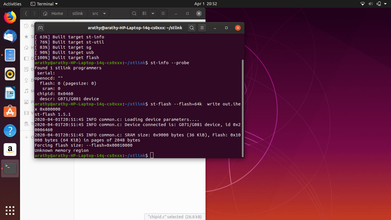
I was trying to flash the code to STM32F103C8 with STLINK-V2 in linux enviornment. When i run the code st-info --probe,below was displayed:
arathy@arathy-HP-Laptop-14q-cs0xxx:~$ st-info --probe
Found 1 stlink programmers
serial:
openocd: ""
flash: 0 (pagesize: 0)
sram: 0
chipid: 0x0460
descr: G071/G081 device
The stlink is detecting but is not able detect the sram and flash memory. Can anyone tell me what could be the reason?
And when i tried to burn the code, this is the result.
I am stuck in this problem,Can anyone please help me to get through this?
Thanks in advance.
 Arathy760
All 30 comments
Please update to the latest release first, before we can offer any support.
 Nightwalker-87
on 2 Apr 2020
Nightwalker-87
on 2 Apr 2020
I am currently using the 1.5.1 version
Arathy760
on 2 Apr 2020
I know, that 's why I asked you to update to the latest version which is 1.6.0.
Nightwalker-87
on 2 Apr 2020
Sir,
As I am new to STM32 and STLINK can you please help me to update it?
Arathy760
on 2 Apr 2020
Please check your ubuntu package repository first.
If v1.6.0 is not available there, please take a look at our documentation in /doc/compiling.md.
Nightwalker-87
on 2 Apr 2020
Sir
The version of stlink in my system is 1.6.0 as shown.

But the version showing in the st-util is 1.5.1.
Arathy760
on 2 Apr 2020
Something is not correct there. Please uninstall this package via the package manager and compile from source as described in the documentation above. I'll take a look at the package - that's another problem.
Apart from that: Your device is not detected correctly.
No device information is displayed when calling st-info --probe:
serial:
openocd: ""
These values should fill out.
chipid: 0x0460
descr: G071/G081 device
These values are not correct for the STM32F103C8. They should be:
 chipid: 0x0410
 descr: F1 Medium-density device
Looks to me as if you caught a fake board/chip.
Nightwalker-87
on 2 Apr 2020
Sir,
This version issued got solved and i think the chipid is correct as i am using a custom board. Now i am facing the first error i.e,the unknown memory region.
Arathy760
on 3 Apr 2020
Please also tell us how you have solved the version issue you had before.
Regarding the device identification something is technically NOT correct, even if you use a custom board. Three possibilities:
1) If you had a STM32F103C8 (ARM-Cortex M3) this would definitely show up with:
 chipid: 0x0410
 descr: F1 Medium-density device
2) If you have a G0 chip (ARM-Cortex M0+) it will show up as seen:
chipid: 0x0460
descr: G071/G081 device
The M0+ and M3 are physically _totally different_ MCU architectures.
3) The chip is defective or not functional. This would also explain why no serial number is displayed and the error unknown memory region appears. Thus the device is not recognised and you can not do _anything_ with it in this case.
Please understand that we can't help you any further, as long as you don't provide more detailed information about your hardware (maybe even an additional image). Also you should take a look at our project documentation: /doc/tutorial.md -> "Using the GDB server" to help find out more about what is wrong with your hardware.
Nightwalker-87
on 3 Apr 2020
Sir,
The version issue is solved when I removed the 1.5.1 version package through package manager.
Arathy760
on 3 Apr 2020
What is your ubuntu version? I'll look at the pkg-version issue then.
You should gain additional info about your device/board in the meanwhile.
I'd prefer to see a gdb console output as described in the tutorial for example.
Nightwalker-87
on 3 Apr 2020
Sir,
Thank you so much for your support,patience and time. I succeeded in solving the unknown memory region issue, When i tried to burn the hex code of my project without specifying a particular address location.
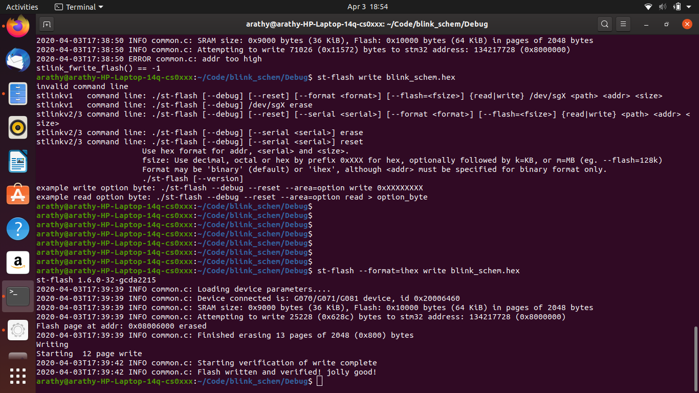
Once again Thank you so much.
Arathy760
on 3 Apr 2020
I see - good, but this also shows clearly that you don't have a STM32F103C8 device, so the issue title is wrong. What chip model is it instead? Can you print out the marking?
It would be nice though, if you addressed the questions I passed over to you, because other users may want to learn something from this as well.
Nightwalker-87
on 3 Apr 2020
... and please run st-info --probe again and let us know about the output.
Nightwalker-87
on 3 Apr 2020
Sir,
As you see i was able to flash the code but when you told me to run st-info --probe it was showing like this

Earlier it was running fine and was displaying me all the details correctly but now its not detecting the device. I think the bootloader is overwritten. How can I get through this?
Arathy760
on 3 Apr 2020
I don't think this is the reason. LIBUSB_ERROR_PIPE denotes a connection problem.
Can you do me a favor forget everything seen so far and restart from the very beginning by following theses steps one by one (without doing anything else not mentioned here):
1) unplug the device
2) write down the marking printed on the chip
3) take a closeup picture of the board (where one is able to recognize some details) and post it here
4) check the soldering - how does it look like? is it done nicely on all pins?
5) connect the board to the programmer again and connect the latter to the PC
6) run st-flash erase, post the output here
7) run st-info --probe, post the output here
... and you still didn't tell me your version of Ubuntu, what prevents me from being able to analyse the pkg-error present in the respective repository.
I'll continue with this as soon as all these points have been fully addressed. It's hardly possible to look at your problem properly, if one jumps from one point to the other and back again - it does not work that way. Please consider this and proceed stepwise and in somewhat logical order.
Nightwalker-87
on 3 Apr 2020
Sir,
I am really sorry for switching from one issue to another.
My Ubuntu version is 19.10
The things which you specified will update soon.
Arathy760
on 3 Apr 2020
Hello Sir,
I did connection of the device as per your instruction.
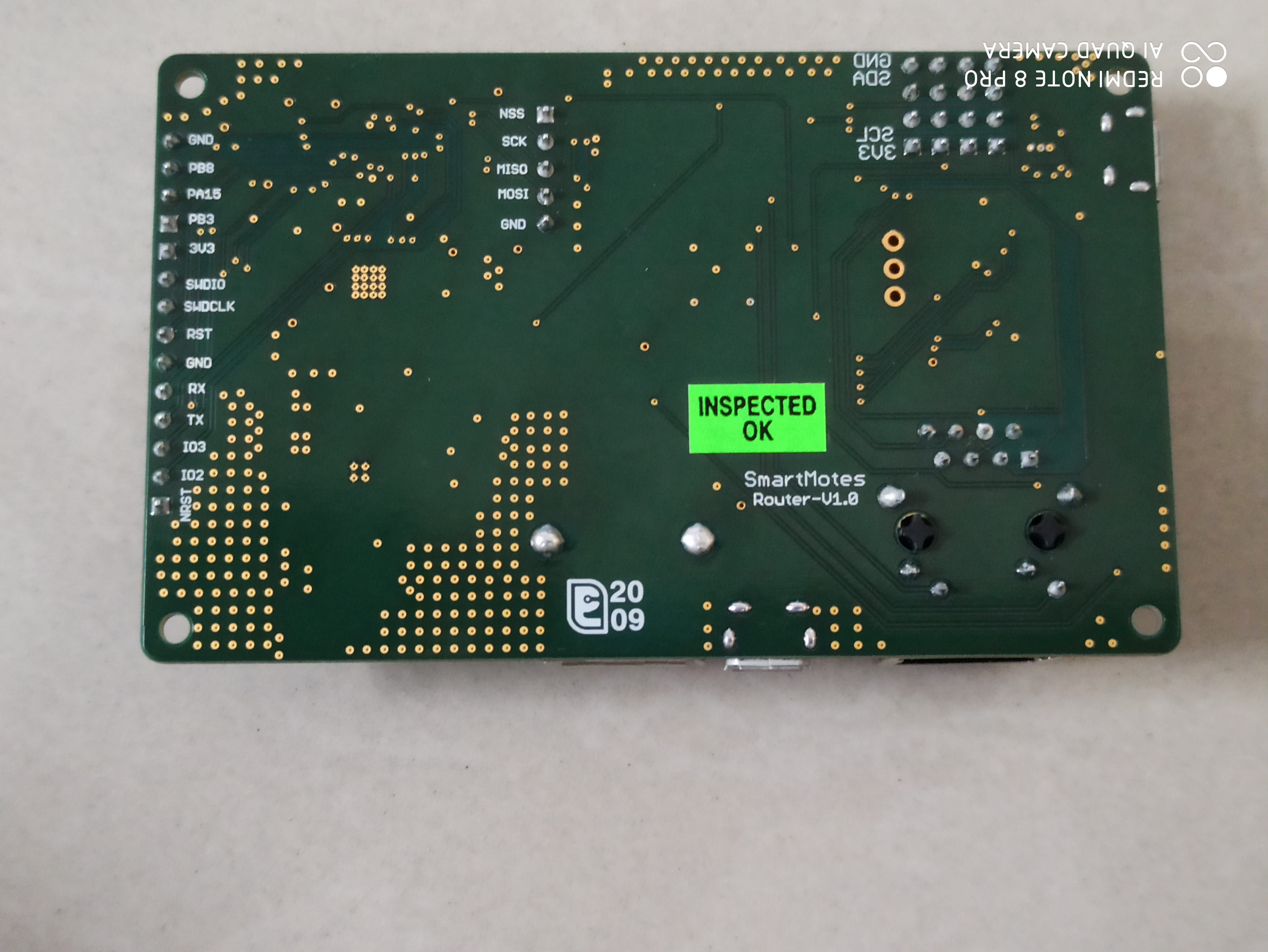
This is my board.


These are output which i got.
Arathy760
on 4 Apr 2020
Thanks.
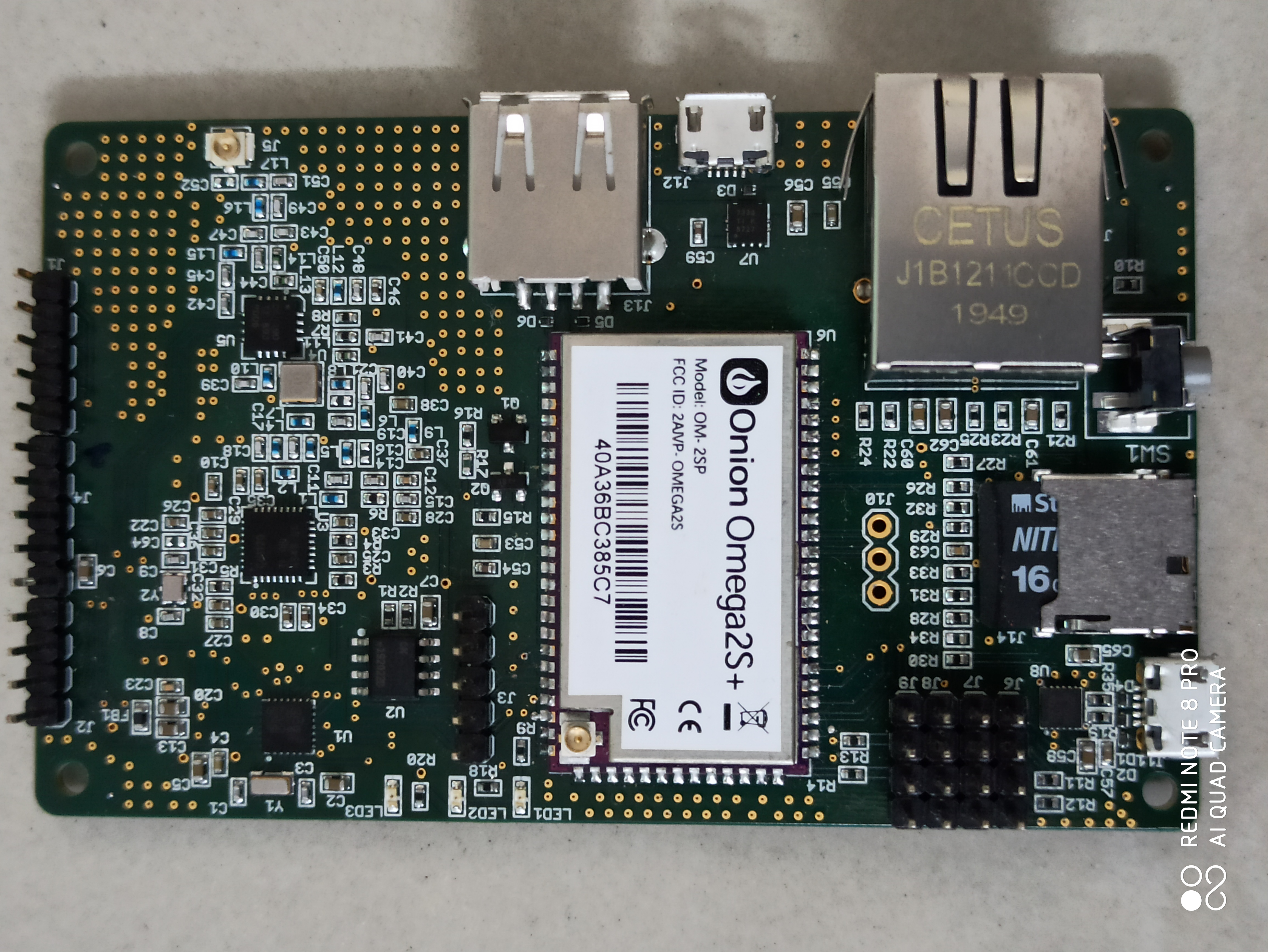
8) Can you write down the printed marking of the ICs at U1 and U3? I believe one of these is the STM32 device. I'm not able read it from the picture you have uploaded.
9) What programmer do you use? Please provide a short description.
I have a STLink-v2 (clone) here which is definitely working, but when I don't connect it to a device (open SWD-wires, on purpose) I find:
$ st-info --probe
[!] send_recv read reply failed: LIBUSB_ERROR_PIPE
[!] send_recv STLINK_DEBUG_RESETSYS
[!] send_recv read reply failed: LIBUSB_ERROR_PIPE
[!] send_recv STLINK_DEBUG_READCOREID
[!] send_recv read reply failed: LIBUSB_ERROR_PIPE
[!] send_recv STLINK_JTAG_READDEBUG_32BIT
Found 1 stlink programmers
and
$ st-flash erase
st-flash 1.6.0-103-g808d2de-dirty
[!] send_recv read reply failed: LIBUSB_ERROR_PIPE
[!] send_recv STLINK_DEBUG_RESETSYS
[!] send_recv read reply failed: LIBUSB_ERROR_PIPE
[!] send_recv STLINK_DEBUG_READCOREID
2020-04-04T12:31:24 ERROR common.c: Failed to read core_id
[!] send_recv read reply failed: LIBUSB_ERROR_PIPE
[!] send_recv STLINK_JTAG_READDEBUG_32BIT
2020-04-04T12:31:24 WARN common.c: unknown chip id! 0x989680
Which is somehow similar to your output. I conclude from this that you are facing a connection problem here. Could it be that you have connected wires from the programmer to the device to some wrong pins on the board or anything alike (accidentally, without realising). To me this looks like as if (some/all?) device sided wires are open ends.
10) Can you test your programmer with another chip or board?
Nightwalker-87
on 4 Apr 2020
Sir,
- U1 is STM32G071G8U6 and U3 is CC1120
- Programmer is ST Link V2

- As you said I tested with the blue pill board it worked fine.

Arathy760
on 4 Apr 2020
Very good, so we can rule that out as well. You have the same programmer I use.
It seems to work accurately, as the bluepill identifies with the correct dataset.
11) Can you connect the four SWD-wires to the board again and check the pinout of each of the 4 lanes (on the board side)? Is there any datasheet or manual of this SmartMotes Router board I can look at on the web?
12) Do you power this board via the programmer (GND & 3V3) or externally?
Nightwalker-87
on 4 Apr 2020
Sir,
The board which I am using is a custom board designed by our company. And I tried by connecting it again but same issue.
And also I tried with connecting both gnd and 3v3 via programmer and also by connecting gnd via programmer, 3v3 by usb.
Arathy760
on 4 Apr 2020
This leads me to the question if you have access to a second identical board for testing.
Currently we can't rule out that an electrostatic discharge (ESD) event occurred somewhen during your testing that has destroyed the board or any key assembly or part on it what now prevents it from reacting to any commands from the programmer. I can't tell from here.
Nightwalker-87
on 4 Apr 2020
We are currently in a lock down situation so another board is not practically possible sir. I have a doubt like how the discharge will occur? As it was working properly till it get programmed.
Arathy760
on 4 Apr 2020
I can happen with a single touch on the board without further notice if not pre cautious enough.
Read here: https://en.wikipedia.org/wiki/Electrostatic-sensitive_device
Maybe you should consider this, when indicating to deal with such topics in a somehow professional surrounding with commercial interest.
If this should be the reason for the board no longer responding, it is very likely that you can dispose it, as you will hardly ever find out where exactly the event occurred on the board and which components are affected.
Nightwalker-87
on 4 Apr 2020
Edit: This may not even have any relation to your programming attempts...
Nightwalker-87
on 4 Apr 2020
Actually I didn't do anything else other than programming the board. And it was working fine till it get programmed.
Arathy760
on 4 Apr 2020
Yes, maybe, but for that you needed to touch it (e.g. to connect the programmer, etc.). So that could be a possible point in time where such an event could have taken place. I charge up every day at home, and I even feel it sometimes when touching the case of my computer. This is a normal physical effect. Knowing that, I'd at least touch a grounded surface before dealing with any unshielded electronic parts. Usually I use either a grounded discharge mat or an ESD wristband, which is always a good idea to prevent any possible damage.
However looking at this I can currently see no problem with the stlink tools that could explain the problem you are currently facing. To me the seen output just looks like as if nothing was connected to the programmer...
Nightwalker-87
on 4 Apr 2020
Anyway thanks alot for your support sir.
Arathy760
on 4 Apr 2020
You are welcome and I hope that you can test with a second identical board soon which then leads to success.
If a similar problem should occur there as well, please feel free to submit a new ticket. I am sure that we can proceed a lot quicker by then, as I got know a lot more about the device.
I am closing this as resolved, as it doesn't seem that we can do anything to it now. Though we couldn't manage to get it to work, I hope to have given some useful general advice that helps you along for upcoming projects.
Nightwalker-87
on 4 Apr 2020
Related issues
 bolorkhuu
·
11Comments
bolorkhuu
·
11Comments
 WRansohoff
·
14Comments
WRansohoff
·
14Comments
 purjus74
·
12Comments
purjus74
·
12Comments
 smartHarsh
·
9Comments
smartHarsh
·
9Comments
 gorynch
·
5Comments
gorynch
·
5Comments